Posts

Air Entrainment – A distant cousin of Cavitation

Image
  Air Entrainment  – A distant cousin of Cavitation Imagine that you are stuck in a locked room, wanting to go out but there is no escape. How much torture would that be for you? That is the amount of torture that the liquid experiences when air or vapor gets entrapped in a pump system. Let us discuss about Airlock, how it occurs in the pump system, what are its causes and effects and 4 tips on how to control them, so that you can consider applying them in your pump system rightaway. An air lock or a vapour lock is a restriction or complete stoppage of liquid flow caused by air trapped in pump inlet This is because the centrifugal effect imparted by the impeller vanes onto the liquid causes the air or gas to separate from the liquid. The eye of an   impeller   is an area of low pressure, which is essential for air/gas accumulation. Eventually, the gases increases so much that air/gas bubble volume , preventing the liquid from entering the impeller. This leads to serious perform

Cavitation Explained

Image
  Introduction Popping a bubble can be a pleasant experience and it is a great stress buster. But rotating equipment like a pump would totally disagree this though.     Today,  I am going to talk about this effect called Cavitation, various reasons for its occurrence and make sure you hang around till the end, I will give you  4 tips on how to control them so that you can consider applying this in your  pump systems.   Hello Everyone, this is Karthik, and welcome to the Pump Universe. Let’s Jump In Right away. Cavitation is a process of  formation of vapour bubble, then its journey towards implosion and microjet formation. Let’s look at each phase in detail. Cavitation Phases: Phase 1 – Formation of vapour Vapour is formed by two different ways. First is by heating.   For Eg: Let’s  take the case of the  water in a container. At room temperature. The watermolecules in the water have lower energy and moves slowly within the vessel. Whereas when the water is heated, its molecules a

Traditional Sealing Methods

Image
Introduction Let us start this session with a question. Which pump part contributes to most % of pump failures?    As per the survey by Euro pumps association, 39% of the pump failures are contributed by the shaft seal ( highest among the equipment) Also, the shat seal contributes to 44% of pump repair costs. Shaft sealing and its failures seem to be the most challenging equipment to maintain in the pump system. Good Day Everyone, This is Karthik and Welcome to the Mag Sealless Pump Basics for process industries. Overview A brief overview of this lesson. Firstly,    Traditional sealing methods and their limiting factors. Secondly, Magnetic coupling, Demagnetization ( Cause and effect)    Then, the  ETFE Lined Pumps It’s advantages and essential accessories to ensure reliable operation. Typical Applications of our previous installations, so that you can consider to apply it in a similar application of yours. Then, a bit about  PP/PVDF Mag Drive Pumps Traditional Sealing Methods Now

Specific Speed and Suction Specific Speed of a Pump

Image
Is the Max Suction specific speed value is   11000 US Units to ensure wider operating range. Let's look at this section. First let's talk about Specific speed.   Specific Speed Specific Speed is a Dimensionless Number indicates the impeller geometry   It has components of speed, Flow at BEP , Differential Head at BEP all for the max impeller condition.   High Ns refers to Axial flow or propeller impellers ( > 9000 Units) and is responsible for larger flow rates.   Low Ns   refers to radial flow/Centrifugal impellers (< 4000 US Units) which provides higher heads.   Medium Ns values refers to Mixed flow Impellers ( 4000- 9000 US Units) which provides a bit of both.  Suction Specific Speed  Suction Specific Speed is in reference to impeller eye   design and is an indicator of suction performance. It has components of Speed in RPM, Flow/ Impeller eye at Best Efficiency Point, NPSHR at Best Efficiency Point all of them derived from the maximum impeller

NPSH and Cavitation

Image
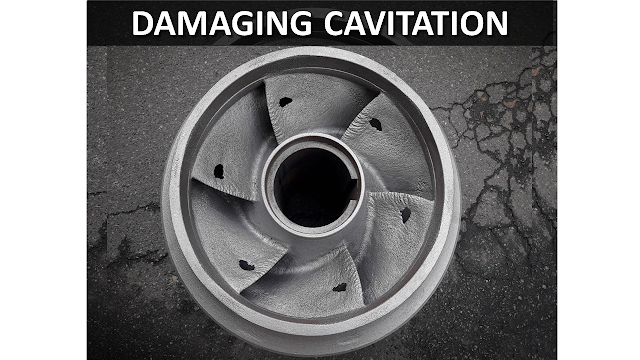
Damaging cavitation can lead to pits on pump components especially the impeller and lead to catastrophic pump failure.   Hence, understanding the Net Positive Suction Head and its impact helps us to operate the pump without major implications.   Net Positive Suction head as the name goes by, is the Net Suction head that you need to have in the pump system to avoid the damaging cavitation.   The truth of the matter is, there will always be cavitation or the presence of vapor bubbles.   Hence, our responsibility is to make sure that the Net Suction Head is abundant which reduces the vapor bubble volume and hence avoids the damaging cavitation.   NPSHA is the Net Suction Head of the system    minus the Vapour Pressure Head     Suction Head of the system has components such as   Surface Pressure Head at suction (Hpa) + Static Suction Head (Hss)   - Friction Loss Head at suction (Hfs ).   All of them derived from the absolute pressure values. Add caption   You

Pump Total Differential Head

Image
Let us consider a system curve of a pump system.   A misconception of the total system head can either decrease the output i.e., flow rate  or runs the flow out of the pump hydraulics.   Hence the estimation of TDH plays a vital role prior to the pump sizing.     The total differential head has two components, Discharge Head and Suction Head.  It is basically   a difference between the total discharge head and total suction head   Now let's look at the suction head   Suction head has three components in their calculation, static suction head (hss), pressure head ( hps) &   friction loss head at suction (hfs)   Where   Static suction head is the elevation height from the suction level to the suction flange.   If the suction is from the below the centreline of the pump, then it is called suction lift and it is expressed in a negative value.   Then the surface pressure at the inlet side. It is zero for atm tank/ sump   Then friction loss at suct

Bernoulli's Principle

Image
Will you be surprised to know that cycling across the slopes and centrifugal pumping principle follow the same rule. Well, it is .. Just like how you cycle across the slopes. While riding upward, you notice that you spend lots of your energy but the cycle rides slowly. This is the phase of an increase in potential energy. Then you reach the top with the highest potential energy.  Whereas while riding downward, your potential energy is spent and you notice that you right faster with less or no effort is spent. This is the phase of kinetic energy.  This phenomenon is called of energy transforming from one phase to the other is called the law of conservation of energy.  Bernoulli's Principle Bernoulli's principle is derived from the law of conservation of energy i.e., pressure energy across the system is a constant regardless of the change of the potential energy or kinetic energy.  Centrifugal pumps work on the basis of this principle i.e, decrease in kinetic energy while the flu